Master Moment of Inertia for Rectangular Plates NOW!

Understanding moment of inertia for a rectangular plate is crucial for engineers and physicists alike. Engineering mechanics, a cornerstone discipline, relies heavily on calculating moments of inertia to predict structural behavior. The parallel axis theorem provides a method for determining the moment of inertia about any axis parallel to the centroidal axis, enhancing practical application. Autodesk Inventor, a popular CAD software, facilitates precise modeling and simulation, assisting in the visualization and calculation of these crucial properties. Researchers at the Massachusetts Institute of Technology (MIT) continue to advance our understanding of material properties and their impact on inertial characteristics, offering new insights into optimizing designs that depend on the precise control of moment of inertia for a rectangular plate.
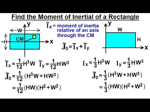
Image taken from the YouTube channel Michel van Biezen , from the video titled Mechanical Engineering: Ch 12: Moment of Inertia (26 of 97) Moment of Inertia=? Rectangle .
The world around us is filled with objects in motion, be it a spinning turbine, a rotating drive shaft, or even a simple seesaw. Understanding how these objects respond to rotational forces is crucial in countless engineering applications. This is where the concept of Moment of Inertia comes into play.
Moment of Inertia, often described as rotational inertia, is a fundamental property that dictates an object's resistance to changes in its rotational motion. Just as mass resists linear acceleration, Moment of Inertia resists angular acceleration.
Moment of Inertia: A Cornerstone of Engineering
Its significance extends across various disciplines, from mechanical and civil engineering to aerospace and robotics. A solid grasp of Moment of Inertia is vital for designing stable structures, efficient rotating machinery, and controlled robotic systems.
Think of designing a bridge: Engineers need to calculate the Moment of Inertia of the beams to ensure they can withstand bending and twisting forces. Or consider a spinning flywheel in an engine: its Moment of Inertia determines how much energy it can store and release, thus smoothing out the engine's power output.
Rectangular Plates: Ubiquitous and Essential
Among the various shapes encountered in engineering, the rectangular plate stands out for its simplicity and widespread use. From structural panels in buildings to electronic circuit boards and machine components, rectangular plates are everywhere.
Their prevalence makes understanding their mechanical behavior, particularly their Moment of Inertia, indispensable. Accurately calculating the Moment of Inertia of a rectangular plate is crucial for predicting its response to applied forces and ensuring structural integrity.
A Comprehensive Guide
This article serves as a comprehensive guide to calculating the Moment of Inertia for rectangular plates. We will delve into the fundamental concepts, explore the relevant formulas, and illustrate their application with practical examples.
Whether you are a student learning the basics of mechanics or a practicing engineer seeking a refresher, this resource will provide you with the knowledge and tools necessary to confidently analyze and design with rectangular plates.
Among the various shapes encountered in engineering, the rectangular plate stands out for its simplicity and widespread use. From structural panels in buildings to electronic circuit boards and machine components, rectangular plates are everywhere.
Their prevalence makes understanding their mechanical behavior, particularly their Moment of Inertia, indispensable. Accurately calculating the Moment of Inertia of a rectangular plate is crucial for predicting its response to applied forces and ensuring structural integrity. But before we dive into the specifics of rectangular plates, it's essential to solidify our understanding of the core concept itself: what exactly is Moment of Inertia?
Demystifying the Core Concept: What Exactly Is Moment of Inertia?
At its heart, Moment of Inertia, also known as rotational inertia, is a measure of an object's resistance to changes in its rotational motion. Think of it as the rotational equivalent of mass in linear motion. Just as a heavier object requires more force to accelerate linearly, an object with a higher Moment of Inertia requires more torque to achieve the same angular acceleration.
This resistance isn't solely dependent on the object's mass; it's also profoundly influenced by how that mass is distributed relative to the axis of rotation.
Area Moment of Inertia vs. Mass Moment of Inertia: Distinguishing the Two
It's crucial to distinguish between two types of Moment of Inertia: Area Moment of Inertia and Mass Moment of Inertia. While both relate to an object's resistance to bending or twisting, they are used in different contexts and calculated differently.
-
Area Moment of Inertia (Second Moment of Area): This property describes a shape's resistance to bending about an axis. It is purely a geometric property, dependent only on the shape's cross-sectional area and its distribution. It is denoted by I with units of length to the fourth power (e.g., in4 or m4). Area Moment of Inertia is critical in structural engineering for designing beams and other structural elements.
-
Mass Moment of Inertia: This describes an object's resistance to rotational acceleration. It depends on both the object's mass and the distribution of that mass relative to the axis of rotation. It is denoted by J or I with units of mass times length squared (e.g., kg⋅m² or lb⋅ft⋅s²). This is essential for analyzing rotating machinery, flywheels, and other dynamic systems.
The key takeaway: Area Moment of Inertia deals with a shape's resistance to bending, while Mass Moment of Inertia deals with an object's resistance to changes in its rotational motion.
The Axis of Rotation: A Critical Consideration
The Moment of Inertia is not an inherent property of an object alone; it is always defined with respect to a specific axis of rotation. Changing the axis of rotation dramatically alters the Moment of Inertia value.
Imagine spinning a pencil. It's much easier to spin it around its long axis (like twirling it between your fingers) than it is to spin it around an axis perpendicular to its length (like spinning it on its end). This is because the mass is distributed differently relative to each axis.
The further the mass is from the axis of rotation, the greater the Moment of Inertia.
This principle is fundamental in engineering design. For example, in designing a rotating shaft, engineers carefully consider the placement of components to minimize the Moment of Inertia, thereby reducing the energy required to accelerate or decelerate the shaft.
Understanding the relationship between the axis of rotation and the Moment of Inertia is paramount for accurate calculations and effective design.
Area Moment of Inertia and Mass Moment of Inertia, while distinct, work together to help us understand how a part reacts under loading. Now, let's shift our focus to the specific geometry that's the star of this article: the rectangular plate. To accurately calculate its Moment of Inertia, we need to understand its defining characteristics and how they impact the calculations.
The Rectangular Plate: Defining Geometry and Key Properties
The rectangular plate, seemingly simple, demands a clear understanding of its geometric properties before we can delve into Moment of Inertia calculations.
Three primary dimensions define a rectangular plate: width, height, and thickness. These parameters are not merely descriptive; they directly influence the object's resistance to bending and twisting.
Width, Height, and Thickness: The Geometric Foundation
The width is the longer dimension of the rectangle, often representing the span of the plate.
The height is the shorter dimension, perpendicular to the width.
The thickness defines the plate's depth, the dimension perpendicular to both width and height.
These three parameters, though basic, form the foundation upon which all subsequent calculations are based.
Changes in any of these dimensions will significantly alter the Moment of Inertia. For instance, increasing the height has a more pronounced effect than increasing the width, due to the cubic relationship in the Moment of Inertia formula.
Density: Bridging Geometry and Mass
While the Area Moment of Inertia relies solely on geometric properties, calculating the Mass Moment of Inertia introduces another critical factor: density.
Density, defined as mass per unit volume, bridges the gap between geometry and mass distribution.
A material with a higher density will inherently possess a greater resistance to rotational acceleration compared to a less dense material with identical dimensions.
Therefore, accurately determining the density of the rectangular plate is essential for precise Mass Moment of Inertia calculations.
Material data tables or direct measurement can determine the density. Understanding Density is therefore vital for understanding a material's resistance to change.
Locating the Centroid: The Center of It All
The centroid represents the geometric center of the rectangular plate. For a uniform rectangular plate, the centroid is located at the intersection of its diagonals, precisely halfway along its width and height.
Finding the centroid is not just a geometric exercise; it is crucial for Moment of Inertia calculations. The simplest Moment of Inertia calculations are performed with respect to axes that pass through the centroid.
Furthermore, the Parallel Axis Theorem, which we will discuss later, relies on knowing the distance between the centroid and another axis of interest.
Therefore, understanding how to locate the centroid accurately is critical for accurate and efficient calculations of Moment of Inertia.
Area Moment of Inertia and Mass Moment of Inertia, while distinct, work together to help us understand how a part reacts under loading. Now, let's shift our focus to the specific geometry that's the star of this article: the rectangular plate. To accurately calculate its Moment of Inertia, we need to understand its defining characteristics and how they impact the calculations.
Formulas in Action: Calculating Moment of Inertia for Rectangular Plates
Now that we've established a firm grasp on the properties of rectangular plates, we can move on to the core of the matter: the formulas that allow us to calculate their Moment of Inertia. These formulas, while appearing concise, are powerful tools that unlock a deeper understanding of how these plates behave under stress.
Unveiling the Formulas: Area Moment of Inertia
The Area Moment of Inertia, often denoted as I, quantifies a shape's resistance to bending about a specific axis. For a rectangular plate, the formulas vary depending on the axis of rotation. Let's examine the most common scenarios:
Rotation About the Centroidal Axis
The centroidal axis is an axis that passes through the centroid of the rectangular plate. The centroid is the geometric center of the rectangle. For rotation about the x-axis (parallel to the width, b), the formula is:
Ix = ( b h3 ) / 12
Where:
- b is the width of the rectangle.
- h is the height of the rectangle.
Similarly, for rotation about the y-axis (parallel to the height, h), the formula is:
Iy = ( h b3 ) / 12
Notice the cubic relationship between the height and width, and the Moment of Inertia. This highlights that increasing the dimension perpendicular to the axis of rotation has a much greater impact on the Moment of Inertia.
Rotation About an Edge
Sometimes, we need to calculate the Moment of Inertia about an axis that coincides with one of the edges of the rectangular plate.
For rotation about an axis along the width (b), the formula becomes:
I = ( b h3 ) / 3
For rotation about an axis along the height (h), the formula becomes:
I = ( h b3 ) / 3
As you can see, the formulas are similar to the centroidal axis formulas, but without the division by 4 (since 3 is 12 / 4). This change is a direct result of shifting the axis of rotation away from the centroid, which we'll explore in detail later with the Parallel Axis Theorem.
A Glimpse into the Derivation: The Power of Integration
While we won't delve into complex calculus, it's helpful to understand the fundamental concept behind these formulas: integration.
Imagine dividing the rectangular plate into infinitesimally small areas (dA). Each of these tiny areas contributes to the overall Moment of Inertia. Integration allows us to sum up these contributions over the entire area of the rectangle, taking into account the distance of each dA from the axis of rotation.
The general formula for Area Moment of Inertia is:
I = ∫ r2 dA
Where r is the perpendicular distance from the area element dA to the axis of rotation. By performing this integration with the appropriate limits for a rectangle, we arrive at the formulas presented above.
Putting Formulas to Work: Example Calculations
Let's solidify our understanding with a couple of practical examples.
Example 1: Centroidal Axis Rotation
Consider a rectangular plate with a width of 10 cm and a height of 5 cm. Let's calculate the Area Moment of Inertia about the x-axis (through the centroid):
Ix = ( b h3 ) / 12 Ix = ( 10 cm (5 cm)3 ) / 12 Ix
**= 104.17 cm4
Example 2: Rotation About an Edge
Now, let's calculate the Area Moment of Inertia of the same plate about an axis coinciding with its width:
I = ( b h3 ) / 3 I = ( 10 cm (5 cm)3 ) / 3 I** = 416.67 cm4
Notice that the Moment of Inertia is significantly larger when the rotation is about an edge, as the material is distributed further away from the axis of rotation.
Realistic Example: Design Application
Imagine you're designing a small platform made of a rectangular steel plate. The plate is 300 mm wide, 200 mm high, and 10 mm thick. You need to determine its resistance to bending when a load is applied along its width.
First, calculate the Area Moment of Inertia about the x-axis (assuming the load will cause bending about this axis):
Ix = ( b h3 ) / 12 Ix = ( 300 mm (200 mm)3 ) / 12 Ix* = 200,000,000 mm4 or 2 x 108 mm4
This value, along with the material properties of the steel, will be crucial in determining the platform's deflection and stress under the applied load, ensuring a safe and reliable design. This Ix would be one component within an overall deflection equation that would give you the total expected deflection given an expected maximum load.
By understanding the formulas and applying them correctly, you can confidently calculate the Moment of Inertia of rectangular plates and use this knowledge to solve a wide range of engineering problems.
Mastering the Parallel Axis Theorem: Shifting Perspectives
Understanding the Moment of Inertia about an object's centroid is often the starting point, but what happens when we need to analyze rotation about a different axis? This is where the Parallel Axis Theorem comes into play, offering a powerful tool for calculating Moment of Inertia about any axis parallel to the centroidal one.
This theorem significantly simplifies complex calculations and expands the applicability of Moment of Inertia principles.
Introducing the Parallel Axis Theorem
The Parallel Axis Theorem provides a method for determining the Moment of Inertia of an object about an axis that does not pass through its centroid, but is parallel to an axis that does.
Think of it as shifting your perspective, allowing you to analyze rotational behavior from different reference points.
The theorem essentially "transfers" the known Moment of Inertia about the centroid to a parallel axis located at a specific distance.
The Formula Unveiled
The Parallel Axis Theorem is expressed mathematically as:
I = Ic + A d2
Where:
- I is the Moment of Inertia about the new axis.
- Ic is the Moment of Inertia about the centroidal axis.
- A is the area of the shape.
- d is the perpendicular distance between the centroidal axis and the new axis.
Each component plays a vital role in accurately calculating the shifted Moment of Inertia. Understanding their individual contributions is key to mastering the theorem.
Deconstructing the Formula Components
Let's break down each element of the formula for clarity:
-
Ic (Moment of Inertia about the Centroid): This is the baseline value, representing the object's resistance to rotation about its center of mass. It's usually a known value or can be calculated using standard formulas.
-
A (Area of the Shape): This refers to the cross-sectional area of the object perpendicular to the axis of rotation. For a rectangular plate, it's simply the product of its width and height (b * h).
-
d (Distance between Axes): This is the critical element that accounts for the shift in the axis of rotation. It's the perpendicular distance between the centroidal axis and the new axis about which you want to calculate the Moment of Inertia.
Applying the Parallel Axis Theorem: Example Calculations
Let's consider a rectangular plate with a width (b) of 10 cm and a height (h) of 20 cm. We want to calculate the Moment of Inertia about an axis parallel to the centroidal x-axis, located 5 cm away.
-
Calculate Ic: The Moment of Inertia about the centroidal x-axis (Ix) is (b h3) / 12 = (10 cm (20 cm)3) / 12 = 6666.67 cm4.
-
Calculate A: The area of the rectangular plate is A = b h = 10 cm 20 cm = 200 cm2.
-
Determine d: The distance between the centroidal x-axis and the new axis is given as 5 cm.
-
Apply the formula: I = Ic + A d2 = 6666.67 cm4 + 200 cm2 (5 cm)2 = 6666.67 cm4 + 5000 cm4 = 11666.67 cm4.
Therefore, the Moment of Inertia about the new axis is 11666.67 cm4.
Practical Benefits and Importance
The Parallel Axis Theorem offers several advantages in engineering analysis:
-
Simplifies Complex Geometries: It allows engineers to analyze the Moment of Inertia of complex shapes by breaking them down into simpler components and applying the theorem to shift the Moment of Inertia to a common reference point.
-
Facilitates Structural Analysis: In structural design, it's crucial for calculating the stress and strain distribution in beams and other structural elements subjected to bending.
-
Enhances Design Optimization: By accurately determining the Moment of Inertia about various axes, engineers can optimize the shape and dimensions of components to achieve desired strength and stiffness characteristics.
In conclusion, the Parallel Axis Theorem is an indispensable tool for any engineer or physicist working with rotational dynamics and structural mechanics. Its ability to "shift perspectives" provides a flexible and efficient method for analyzing the Moment of Inertia about various axes, leading to more accurate and optimized designs.
Mastering the Parallel Axis Theorem provides a powerful method for calculating Moment of Inertia about any axis parallel to the centroidal one. But what about scenarios where the force isn't applied in a single plane, where twisting or torsion becomes the dominant factor?
Understanding Polar Moment of Inertia: Torsion and Rotation
In the realm of structural mechanics, understanding how an object resists twisting forces is just as crucial as understanding its resistance to bending. This is where the Polar Moment of Inertia comes into play.
It describes an object's ability to resist torsion due to an applied torque. It's particularly important when dealing with shafts, axles, and other components subjected to twisting loads.
Defining Polar Moment of Inertia
Unlike the standard Area Moment of Inertia, which concerns resistance to bending, the Polar Moment of Inertia focuses on resistance to torsion or twisting.
Think of it as a measure of an object's "torsional stiffness." A higher Polar Moment of Inertia indicates a greater resistance to twisting under an applied torque.
It is always calculated about an axis perpendicular to the cross-sectional area of the object, usually passing through its centroid.
Polar Moment of Inertia and Torsional Loads
The significance of the Polar Moment of Inertia becomes clear when analyzing structures subjected to torsional loads. Torsional loads create shear stresses within the object.
The magnitude of these stresses is inversely proportional to the Polar Moment of Inertia.
This means a component with a higher Polar Moment of Inertia will experience lower shear stresses under the same torsional load, making it less likely to fail due to twisting.
Applications can be found everywhere, from the drive shafts in vehicles to the structural supports of buildings designed to withstand wind loads.
The Relationship to Area Moment of Inertia
For rectangular plates, and indeed for many shapes, the Polar Moment of Inertia (J) has a direct relationship to the Area Moments of Inertia about two perpendicular axes (Ix and Iy) within the plane of the object.
The relationship is expressed by the following equation:
J = Ix + Iy
Where:
- J is the Polar Moment of Inertia.
- Ix is the Area Moment of Inertia about the x-axis.
- Iy is the Area Moment of Inertia about the y-axis.
This simple, yet powerful relationship allows engineers to calculate the Polar Moment of Inertia using previously determined Area Moments of Inertia. It can significantly simplify calculations, particularly when dealing with standard geometric shapes like our rectangular plate.
In essence, the Polar Moment of Inertia combines the resistance to bending about two perpendicular axes to provide a measure of the object's resistance to twisting. This understanding is essential for analyzing structural integrity under torsional forces.
Understanding the principles and formulas behind Moment of Inertia is only half the battle. Consistent and correct application hinges on using the right units.
Units and Conversions: Precision is Key
In the realm of engineering calculations, particularly when dealing with Moment of Inertia, accuracy reigns supreme. The numerical value is meaningless without the correct units attached. Using the wrong units can lead to drastically incorrect results. That leads to potentially catastrophic consequences in structural designs and analyses.
The Importance of Unit Consistency
The Moment of Inertia is typically expressed in kg m² (kilogram meters squared) in the metric system. In the imperial system, it's expressed as lbf in² (pound-force inch squared). These units reflect the parameters used in the calculations: mass or force and distance.
Using the appropriate units ensures that the results are consistent with the overall system of units used in the problem. Inconsistent units will propagate errors through the calculations, leading to inaccurate predictions and potentially unsafe designs.
Common Units and Conversion Factors
While kg m² and lbf in² are the most common, you might encounter other variations depending on the context:
- Metric: g cm² (gram centimeter squared), kg mm² (kilogram millimeter squared)
- Imperial: lbm ft² (pound-mass foot squared), slug ft²
To ensure accuracy, it's essential to be able to convert between these units. Here are some common conversion factors:
- 1 kg m² = 10,000 g cm²
- 1 m = 1000 mm
- 1 inch = 0.0254 meters
- 1 lbf = 4.448 Newtons
- 1 kg = 2.205 lbm (pound-mass)
These conversion factors allow you to transform values from one unit system to another. Ensuring consistency throughout your calculations is essential.
Practical Examples of Unit Conversion
Let's look at a couple of examples to illustrate how unit conversions work:
Example 1: Convert 5 kg m² to g cm²
- 5 kg m² (1000 g / 1 kg) (100 cm / 1 m)²
- = 5 1000 100² g cm²
- = 50,000,000 g cm²
Example 2: Convert 10 lbf in² to kg m²
- 10 lbf in² (4.448 N / 1 lbf) (0.0254 m / 1 in)²
- = 10 4.448 0.0254² kg m²
- ≈ 0.0287 kg m²
By carefully applying these conversion factors, you can confidently switch between unit systems. This will help ensure that your Moment of Inertia calculations are accurate and reliable.
The Interplay Between Units and Formulas
The formulas for calculating Moment of Inertia are derived based on specific units. The units of the input parameters (like mass, length, or area) must align with the expected units in the formula.
For example, if a formula expects dimensions in meters, using dimensions in millimeters will result in a dramatically incorrect Moment of Inertia value.
Always double-check the units of your inputs before plugging them into a formula. Also, verify that the resulting units are appropriate for the application. This simple step can save you from costly errors and design flaws.
Real-World Applications: From Theory to Practice
Understanding Moment of Inertia isn’t just about mastering formulas and calculations; it’s about unlocking the ability to analyze and design real-world structures with confidence. The principles we've explored become powerful tools when applied to the challenges faced by engineers every day. Let's explore practical applications where this knowledge is essential.
Moment of Inertia in Engineering Mechanics
Engineering Mechanics relies heavily on the concept of Moment of Inertia. It allows engineers to predict how structural elements will behave under different loading conditions.
Specifically, it's crucial for determining:
- The resistance of a beam to bending.
- The stability of a column against buckling.
- The torsional stiffness of a shaft.
This knowledge is fundamental to ensuring the safety and reliability of any structure.
Structural Design and Analysis: Ensuring Stability
Structural design and analysis are core domains where the Moment of Inertia plays a pivotal role.
Beam Design
When designing beams, engineers must consider the bending moments and shear forces they will experience under load. The Moment of Inertia of the beam's cross-section directly influences its ability to resist bending.
A higher Moment of Inertia translates to a greater resistance to bending, meaning the beam can withstand heavier loads without excessive deflection or failure. Engineers select materials and cross-sectional shapes to achieve the necessary Moment of Inertia for a specific application.
Stress and Strain Analysis
Moment of Inertia is essential in calculating stress and strain distributions within a structural member. When a rectangular plate is subjected to bending, the stress is not uniform across its cross-section.
The areas farthest from the neutral axis (the centroid) experience the highest stress levels. Understanding the Moment of Inertia allows engineers to accurately determine these stress distributions. That helps in ensuring that the material's yield strength is not exceeded, preventing structural failure.
Specific Real-World Examples
Here are some specific examples illustrating how the Moment of Inertia of rectangular plates manifests in real-world engineering scenarios:
- Bridge Design: Bridge decks often incorporate rectangular plates as structural elements. Engineers must calculate the Moment of Inertia of these plates to ensure the bridge can withstand the weight of traffic and environmental loads.
- Aircraft Wings: The wings of an aircraft are subject to complex aerodynamic forces. Rectangular plates are used as stiffening elements within the wing structure. Calculations related to the Moment of Inertia are essential to prevent bending and flutter during flight.
- Building Construction: Rectangular plates are used in the construction of building floors and walls. Engineers must determine their Moment of Inertia to ensure the building can withstand wind loads, seismic forces, and the weight of occupants and equipment.
- Machine Components: Many machine components, such as linkages and brackets, incorporate rectangular plates. The Moment of Inertia is critical for determining their stiffness and resistance to deformation under operational loads.
By carefully considering the Moment of Inertia in each of these applications, engineers can design structures that are safe, efficient, and reliable.
Video: Master Moment of Inertia for Rectangular Plates NOW!

FAQs: Mastering Moment of Inertia for Rectangular Plates
Here are some frequently asked questions to help you better understand the moment of inertia for rectangular plates.
What exactly is moment of inertia?
Moment of inertia is a measure of an object's resistance to rotational acceleration. Think of it as rotational inertia – the higher the moment of inertia, the harder it is to make something spin or change its spin. It depends on both the mass and the distribution of mass relative to the axis of rotation.
How does the shape of a rectangular plate affect its moment of inertia?
The dimensions of the rectangular plate – its length and width – directly impact the moment of inertia. A wider or longer plate will generally have a higher moment of inertia than a smaller one with the same mass. The axis of rotation is also crucial; rotation about different axes yields different moments of inertia.
What's the formula for calculating the moment of inertia for a rectangular plate about its center?
The formula varies depending on the axis of rotation. For rotation about an axis parallel to one of its edges and passing through the center, the formula is typically I = (1/12) * m * a^2, where m is the mass and a is the length of the side perpendicular to the axis of rotation.
Why is understanding the moment of inertia for a rectangular plate important?
The concept is fundamental in engineering and physics. It's crucial for analyzing the behavior of structures, designing rotating components, and understanding how objects respond to forces that cause rotation. Any application involving rotational dynamics relies on correctly calculating the moment of inertia.